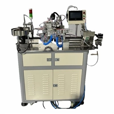
Operational Principle
1. Utilizing computer-controlled servo drive, this system can manufacture various vertical-wound coils with thicknesses ranging from 0.2mm to 6.0mm and widths from 1.0mm to 10mm (with wire cross-sections up to 30mm²).
2. For mechanical debugging of products with different specifications, only the mold needs to be replaced.
3. Multi-station operation, enabling automatic forming of vertical winding coils on the machine
4. The system can store and retrieve machine parameters for products of various specifications, meeting customers' needs for automated production, efficiency improvement, and quality assurance.
Specification
|
Winding Diameter |
Standard: Wire diameter ≤30 mm², width-to-thickness ratio ≤15 times The wire has a maximum width of 15 mm and a maximum thickness of 2.5 mm. |
|
Maximum Height of Coil |
150 millimeters |
|
Going |
7kW transformer with three-phase 380V input and 220V output |
|
Working Air Pressure |
0.4~0.8mpa/cm |
|
Feed Line Method |
Artificial extraction |
|
Maximum Winding Number |
100T (left and right rotation) |
|
Shape of Product |
A〔Tap〕, E2〔Tap〕, D〔Tap〕, K〔Tap〕, single-layer, multi-layer continuous inner circular coil |
|
Production Efficiency |
0~55pcs/min |
|
Dimensions (length*width*height) |
Approximately 1250*850*1650 mm in dimensions, weighing around 800 kg. |
Producing styles: Flat line round hole winding form

Security Considerations
1. Do not open the casing without permission.
2. When the controller is not in use for an extended period, disconnect the power supply.
3. Special attention must be paid to prevent dust and iron powder from entering the control chamber.
4. Handle with care during transportation to avoid damaging the controller.
Precautions for correct use;
Improper usage may cause malfunction, and in worst cases, could even damage the controller.
Therefore, please follow the following precautions for the correct use of the control device.
1. Verify that the connected power supply meets the specifications to prevent controller burnout.
2. The controller's lifespan is significantly affected by ambient temperature. If the processing site temperature is excessively high, installation should be performed.
Cooling fan. The controller supports an operating temperature range of 0°C to 60°C.
3. Avoid use in environments with high temperature, humidity, dust, or corrosive gases.
4. In areas with strong vibrations, rubber shock pads should be installed for cushioning.
Precautions for Maintenance and Inspection
1. The power supply of the main circuit should be disconnected first before performing maintenance and repair on the controller.
2. The operator must personally verify that the power supply is disconnected to prevent accidents.
Check items and cycles
Under standard operating conditions (environmental parameters: daily average temperature 30°C, 80% load rate, 12-hour daily operation), perform routine inspections and periodic checks as specified below.
Maintenance of Mechanical Parts
1. Daily maintenance:
①. Before daily startup, inspect all machine components for normal operation. Clean the surface with a gas gun, wipe the sliding parts, and apply lubricating oil.
②. When cleaning the equipment, avoid directing the air gun at the solder surface or flux cup to prevent injury from molten solder or flux splashes, as well as scalding the airway.
③. Clean up and recycle tin slag and flux residue in time.
2. Regular Maintenance:
①. Apply grease to the grease nozzle area every three months using a grease gun, ensuring the grease flows out cleanly from the gap.
②. Temperature control gauges and barometers shall be calibrated annually, while mechanical components require semi-annual maintenance. Any abnormalities should be addressed through proactive maintenance.
③. If the machine is not in use for an extended period, the surface must be thoroughly cleaned, lubricated, and wrapped with a waterproof rubber cloth to prevent moisture ingress and surface dust contamination.