

The difference between concentrated and distributed winding comes down to coil pitch relative to pole pitch: a concentrated winding puts each coil around a single tooth, while a distributed winding spreads each phase's coils across several slots per pole, overlapping their neighbours.
That one difference changes the winding factor, the harmonic content of the magnetic field, the length of the end turns, and above all how the stator is made. Concentrated coils can be wound directly on the tooth, while distributed coils are usually wound separately and placed into slots lined with insulation.
Below, we define the key terms, work through the winding factor formula with a numerical example, and show which motors use which winding and what each one needs from the production line.

I. What Is the Difference Between Concentrated and Distributed Winding?
| Feature | Concentrated Winding | Distributed Winding |
|---|---|---|
| Coil placement | Around one tooth, no overlap | Across several slots, overlapping |
| Slots per pole per phase (q) | Usually 0.5 or less, often fractional | Usually an integer of 2 or more |
| End turns | Short | Long |
| Magnetic field | More harmonics | Closer to sinusoidal |
| Typical production | Direct tooth winding | Winding plus insertion, or direct slot winding with indexing |
| Typical motors | BLDC, drone, e-bike | Induction, ceiling fan, industrial |
a. the terms you need
Four terms describe how a winding is laid out, and the rest of this article uses them.
| Term | Meaning | Formula |
|---|---|---|
| Pole pitch | Distance between pole centers, in slots | τp = S / P |
| Slot pitch | Angle between adjacent slots | 360° / S mechanical; γ = (P × 180°) / S electrical |
| Coil pitch | Number of slots a coil spans | y (pitch ratio β = y / τp) |
| Slots per pole per phase | How many slots each phase has under one pole | q = S / (P × m) |
S is the slot count, P the pole count, and m the number of phases.
b. why this matters
A concentrated winding has a coil pitch of one slot pitch, far less than the pole pitch, while a distributed winding uses a coil pitch close to the pole pitch. Everything else follows from that ratio.
II. How Do Pole Pitch, Slot Pitch, and Coil Pitch Set the Winding Factor?
The winding factor measures how effectively a winding turns the magnetic field into usable flux linkage. The winding factor formula multiplies two terms:
kw = kd × kp
Distribution factor: kd = sin(q × γ / 2) / (q × sin(γ / 2))
Pitch factor: kp = sin(β × 90°)
Worked example: a 36-slot, 4-pole, 3-phase stator:
Pole pitch τp = 36 / 4 = 9 slots
q = 36 / (4 × 3) = 3
Slot pitch γ = (4 × 180°) / 36 = 20° electrical
kd = sin(3 × 10°) / (3 × sin 10°) = 0.5 / 0.5209 ≈ 0.960
The pitch factor then depends on the coil pitch chosen:
| Coil Pitch | β = y / τp | kp | kw = kd × kp |
|---|---|---|---|
| y = 9 (full pitch) | 1.000 | 1.000 | 0.960 |
| y = 8 (short pitch) | 0.889 | 0.985 | 0.945 |
| y = 7 (short pitch) | 0.778 | 0.940 | 0.902 |
a. example: a coil span error in a fan motor line
Consider a fan motor manufacturer with a single-phase stator of 36 slots and 4 poles, so a pole pitch of 9 slots. Coils are placed by hand, and depending on how carefully each operator sets up, the coil groups span 8 slots on some motors and 7 on others.
Using the table above, the pitch factor alone drops from 0.985 to 0.940, about 4.6% less fundamental flux linkage for the same turns and supply voltage. The result is motor-to-motor variation in speed and current that looks like a wire or magnet problem but is really a coil span problem. Fixing the coil pitch with a winding form and a controlled placement step makes every motor identical on this one parameter.
Seeing unit-to-unit variation in fan or single-phase motors that traces back to coil span or slot filling? Contact our team and tell us your slot and pole count, and we will advise on a machine route.
b. what the table says about short pitch winding
Going from full pitch to y = 8 costs about 1.6% of the winding factor (0.960 to 0.945). Whether that trade is worth making depends on what short pitch winding buys, which the next section covers.
III. When Does Short Pitch Winding Make Sense?
Short pitch winding shortens the coil span below the pole pitch, trading a little winding factor for other benefits.
| Effect of Short Pitching | Result |
|---|---|
| End turns | Shorter, so less copper and lower end-winding resistance |
| Harmonics | Certain harmonics, especially the 5th, are reduced |
| Winding factor | Slightly lower fundamental, as the table above shows |
| Coil overlap | Less crowding of end turns |
a. why harmonics drop
The pitch factor for the nth harmonic is sin(n × β × 90°). For the 5th harmonic at y = 8, this is sin(400°) = sin 40° ≈ 0.64, compared with 1.0 at full pitch, so that harmonic is cut by roughly a third while the fundamental falls only about 1.5%.
b. why it is common in induction motors
Most induction motors use short pitch distributed windings because the copper saving and smoother field outweigh the small loss in fundamental winding factor.
IV. What Is Fractional Slot Winding?
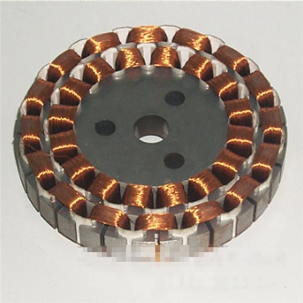
A fractional slot winding has a non-integer q, so the winding pattern repeats only after several poles. This is the normal arrangement for concentrated windings.
| Example | Slots / Poles | q | Winding Type | Typical Winding Factor |
|---|---|---|---|---|
| Integral slot, distributed | 24 / 4 | 2 | Distributed | about 0.966 (full pitch) |
| Fractional slot, concentrated | 12 / 10 | 0.4 | Concentrated | about 0.933 |
a. why fractional slot suits concentrated coils
With q below 1, each coil sits on one tooth and the winding factor stays high enough for good torque, while the short end turns and simple coil shape keep production straightforward.
V. Which Motors Use Which Winding?
| Motor | Winding Type | Notes |
|---|---|---|
| BLDC, drone, e-bike | Concentrated, fractional slot | Power density and fast production |
| Three-phase induction | Distributed, often short pitch | Smooth field, standard industrial motor |
| Ceiling and pedestal fan | Distributed, concentric coil groups | Single-phase construction |
| Servo | Either, depending on torque ripple needs | Smoother torque favors distributed |
a. single phase motor winding in fans
Single phase motor winding uses a main winding and an auxiliary winding in the same stator slots, offset by 90 electrical degrees, with the auxiliary winding working with a capacitor. Both are normally laid as concentric coil groups spread across several slots, so they are distributed windings even though only one supply phase is used.

VI. How Do the Two Types Differ on the Production Line?
The two windings need different steps, different tooling, and different insulation handling.
| Step | Concentrated | Distributed |
|---|---|---|
| Insulation | Insulation on the tooth or bobbin | Slot liner insulation placed in every slot before winding or insertion |
| Winding | Wound directly on the tooth | Wound on a form, or wound directly into slots with indexing |
| Insertion | Not needed | Coil inserting machine pushes formed coils into the slots |
| Coil pitch control | Fixed by the tooth | Set by the form or indexing, must be consistent |
a. slot liner insulation
Slot liners are insulating sheets placed in each slot to keep the wire away from the sharp edges of the laminations. Their material should follow IEC 60626-1, the standard for combined flexible materials for electrical insulation, and a missing or misplaced liner is a common source of insulation faults.
b. the winding-plus-insertion route
For a distributed winding, a coil inserting machine places the pre-formed coil group into the lined slots in one stroke, which keeps coil pitch identical from motor to motor, exactly the parameter that failed in the fan example above.
c. rating and performance requirements
The finished stator must meet the rated performance requirements in IEC 60034-1, the international standard for rotating electrical machines.
VII. Which KIOXIA Machine Fits Your Winding Type?
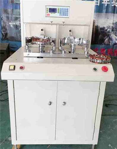
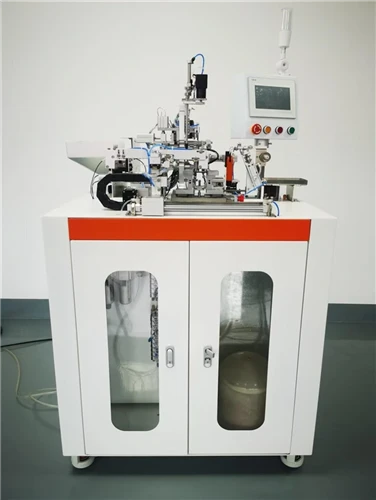
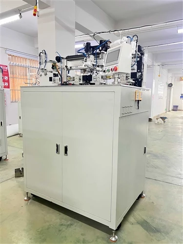
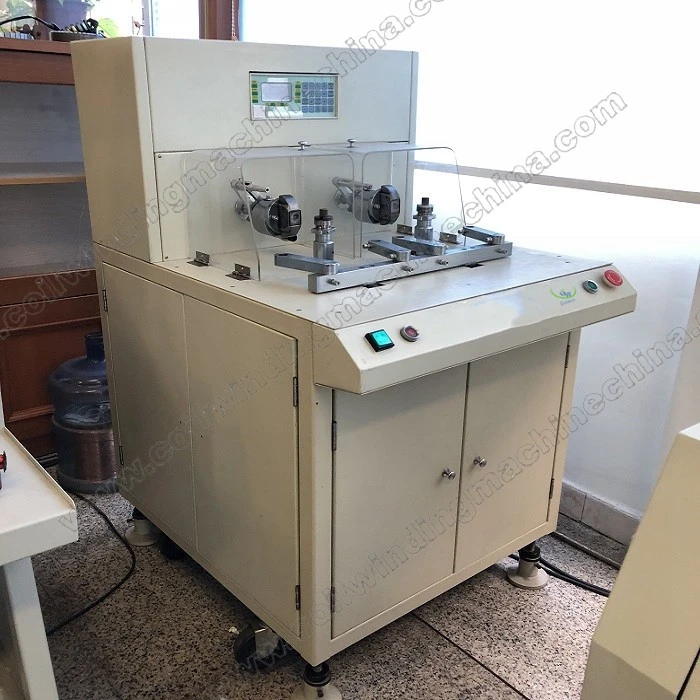
KIOXIA Light Ring Equipment Group's stator range includes a ceiling fan winding machine, a fan motor winding machine for the single-phase, multi-slot distributed windings described above, as well as stator coil production machines for motor lines. Whether you wind directly into slots or wind first and insert, the machine choice depends on your slot and pole combination, wire gauge, and output target.
If you are unsure whether your motor suits concentrated or distributed winding, or which production route fits it, working with an experienced coil winding machine manufacturer on a short spec review is the quickest way to decide.
Explore the full lineup at transformercoilwindingmachine.com to find a stator winding solution for your motor.
You may be interested in:
Overcoming Shuttle and Winding Head Pitch Issues in CNC Toroidal Winding
Concentrated vs Distributed Winding Comparison
Slider Head Winding Tension Adjustment Guide
Toroidal and E-I Transformers: Key Differences and Performance