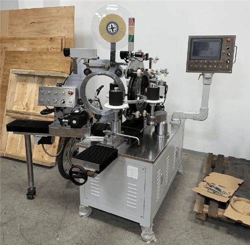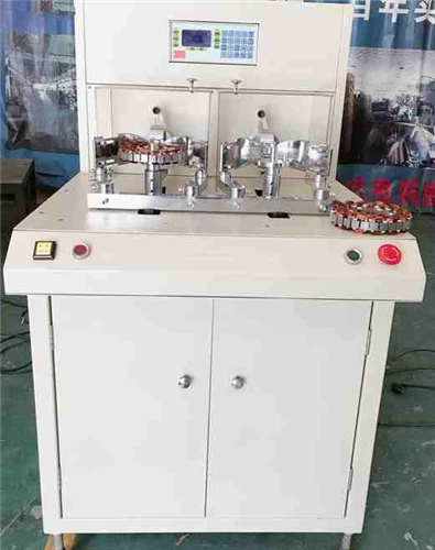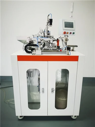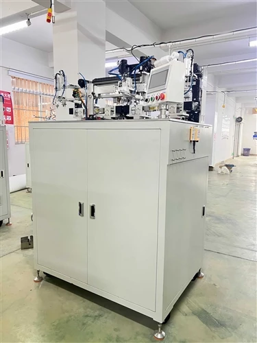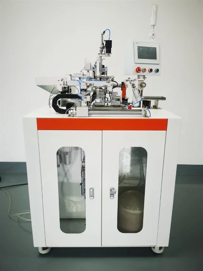


Quick Answer: A coiling machine (coil winding machine) works by rotating a spindle to spin a bobbin, core, or toroidal ring while a synchronized wire-feed mechanism lays enameled wire around it under controlled tension, layer by layer, until a preset turn count is reached - after which the wire is cut and terminated automatically.
Modern automatic coil winders and CNC coil winding machines use servo motors and programmable logic to control winding speed, wire tension, and traverse pitch, allowing the same machine to produce inductor coils, transformer windings, motor stator coils, and toroidal transformer windings with high repeatability.
The rest of this article breaks down each stage of the process, compares spindle winding vs. toroidal winding, and covers the tension and wire-sizing formulas used to set up a winding job correctly.

I. What Is the Basic Working Principle of a Coiling Machine?
At its core, every coil winding machine - whether it's a simple bench-top spindle winder or a fully automatic CNC coil winding machine - performs the same four functions in sequence: unwind, tension, wind, and terminate.
a. wire unwinding and tension control
Wire is drawn from a supply spool through a mechanical or magnetic tensioner. Tension must stay within a narrow band: too loose and the winding becomes uneven or loose (poor coupling, resonance issues); too tight and the enamel insulation can crack or the wire can deform the bobbin or core.
b. spindle rotation and wire placement
The bobbin, core, or stator is mounted on a spindle driven by a motor. As the spindle rotates, a traverse guide (nozzle or flyer) moves in a synchronized path to lay the wire evenly - this is the mechanism behind single-layer winding, multi-layer winding, and precision-pitch winding.
c. turn counting and stop control
An encoder or photoelectric sensor tracks spindle rotations. Once the programmed turn count is reached, the machine automatically slows, stops, and signals for wire cutting or the next process step.
d. wire termination
The wire ends are cut, and on automatic machines, they are also hooked, soldered, or wrapped onto terminal pins without operator intervention.

II. How Does a Toroidal Winding Machine Work Differently?
Unlike bobbin-style spindle winding, a toroidal winding machine has to thread wire through the center hole of a ring-shaped (donut-shaped) magnetic core repeatedly - the core itself does not rotate the way a bobbin does. This is mechanically more demanding and is why toroidal transformer winders form their own equipment category.
a. ring/flyer type toroidal winding
A rotating ring pre-loaded with wire orbits around and through the core, depositing one turn per rotation. This is the most common method for medium-to-high volume toroidal transformer winder production.
b. shuttle type toroidal winding
A shuttle carrying a small wire bobbin physically passes through the core opening and back around it for each turn - slower than ring winding, but suited to larger core diameters or thicker wire gauges where a ring mechanism isn't practical.
c. gear-type toroidal winding
A gear-driven mechanism advances the wire-carrying ring in discrete steps, giving finer control over turn spacing - often used for current transformer winding, where turn-to-turn uniformity directly affects measurement accuracy.
| Toroidal Winding Method | Typical Core Size | Speed | Common Use Case |
|---|---|---|---|
| Ring/flyer type | Small–medium | Fast | High-volume inductor coil winding machine production |
| Shuttle type | Medium–large | Slow–medium | Large power toroidal transformers |
| Gear type | Small–medium | Medium | Current transformer winding, precision CTs |

III. What Are the Main Types of Coil Winding Machines by Application?
Different coil geometries require different machine architectures. The table below maps machine type to typical application.
| Machine Type | Winding Style | Typical Application |
|---|---|---|
| Spindle winding machine | Bobbin rotates on a straight spindle | Inductor winding machine, small transformers |
| Toroidal transformer winder | Wire threads through a ring core | Toroidal transformers, EMI filter cores |
| Motor stator winding machine | Wire wound into stator slots | Motor stator winding machine, generator stators |
| CNC coil winding machine | Servo-controlled multi-axis winding | Complex or variable-pitch custom coils |
| Automatic coil winder | Fully automated feed-wind-cut-terminate cycle | High-volume production of any coil type |
a. spindle winding machines
Used for standard bobbin-based inductor coils and small transformer coil winding machine applications where the coil form is cylindrical.
b. motor stator winding machines
These wind wire directly into the slots of a motor or generator stator core, often using needle winding or linear winding heads rather than a simple rotating spindle, since the coil path follows the stator's slot geometry rather than a straight cylinder.
c. CNC coil winding machines
Programmable, multi-axis machines that can switch between winding patterns via software, making them suited to low-volume, high-mix production or R&D prototyping.

IV. How Is Wire Tension and Wire Size Calculated for Winding?
Correct setup depends on matching wire tension to wire gauge, and confirming the enameled wire's bare copper diameter against the cross-sectional area it needs to carry.
a. wire diameter from cross-sectional area
The bare wire diameter can be derived from the required cross-sectional area using:
d = √(4S / π)
Where:
d = bare (uninsulated) enameled wire diameter (mm)
S = required wire cross-sectional area (mm²), determined by current-carrying capacity
b. winding tension guideline
As a general rule of thumb, winding tension (T) is set proportional to wire diameter squared, since thinner wire tolerates less pulling force before deforming or breaking:
T ≈ k × d²
Where k is a tension coefficient determined empirically per wire type and insulation class (typically supplied by the wire manufacturer or established through test winding).
| Wire Diameter (mm) | Typical Tension Range (approx.) | Risk if Exceeded |
|---|---|---|
| 0.05–0.10 | Very low | Wire breakage |
| 0.10–0.30 | Low–medium | Insulation cracking |
| 0.30–0.80 | Medium | Core/bobbin deformation |
| 0.80+ | Medium–high | Spindle motor overload |
Getting tension right is what separates a consistent, high-yield coil winding machine setup from one with frequent wire breaks and rework - which is also why turn-count accuracy and tension control are usually the first two parameters checked during acceptance testing.
If you're sourcing equipment rather than just researching the mechanism, KIOXIA manufactures a full range of toroidal and coil winding machines covering the categories above - including ring-type toroidal transformer winders, gear-type toroidal winding machines for current transformer production, and automatic coil winders for inductor and stator winding lines.
You may be interested in:
What are common problems with coil winding machines?
How to Design Efficient Toroidal Transformers
The Ultimate Guide to Coil Winding Machines