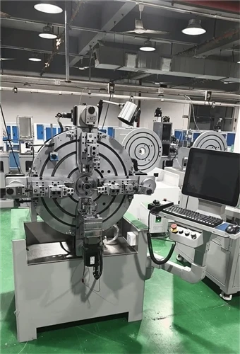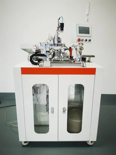


Operating a coil winding machine correctly comes down to getting five things right in sequence: loading the wire, setting up the bobbin or core, configuring turns count and winding pattern, dialing in wire tension, and running a test cycle before full production.
This step-by-step guide walks through the full winding process from power-on to finished coil, covering the tension and speed settings that most affect coil quality, along with the math behind calculating winding time and turns - whether you're producing transformer winding, inductor winding, or motor coil winding on the same machine.
Below, we break it down stage by stage, with a real example of how a small setup mistake commonly derails a first production run.

I. What Should You Check Before Powering On the Machine?
Before any wire touches the spindle, a quick pre-check prevents the majority of first-run problems operators encounter.
a. inspecting the machine and workspace
Confirm the wire guides, tensioner, and spindle chuck are clean and undamaged, and that the workspace around the machine is clear - small wire scraps or loose tools near the spindle are a common source of avoidable stoppages.
b. matching the machine setup to your job
Confirm the bobbin or core, wire gauge, and target coil specification match what the machine is currently configured for - running the wrong wire gauge through guides sized for a different diameter is one of the most common causes of wire damage on a first attempt.
II. How Do You Load Wire and Set Up the Bobbin?
Correct wire loading and bobbin setup form the physical foundation the rest of the winding process depends on.
a. threading the wire through guides and tensioner
Feed the wire through each guide and the tensioner in the sequence specified for your machine, checking that it sits properly in each guide's groove rather than resting against an edge, which can cause abrasion during winding.
b. mounting the bobbin or core
Secure the bobbin, core, or mandrel onto the spindle chuck, confirming it's centered and seated firmly - a loosely mounted bobbin is a common cause of uneven bobbin winding and inconsistent turn spacing.

III. How Do You Set Tension, Speed, and Winding Pattern?
This is the stage where most coil quality issues originate, since wire tension control, spindle speed, and winding pattern settings directly determine the finished coil's consistency.
a. real-world example: a common first-run mistake
A new operator running a small transformer bobbin coil for the first time left the tension setting at the machine's previous job default - configured for a much heavier wire gauge than the fine wire now being used.
The result was a coil with visibly loose, uneven layers and several wire breaks partway through the run, traced entirely back to the mismatched tension setting rather than any fault in the wire or machine itself. Resetting tension to match the new wire gauge, then running a short test cycle before full production, resolved the issue completely on the next attempt.
If you're setting up a new coil job and want help getting tension and speed settings right the first time, reach out to our team - we're happy to walk through your specific wire gauge and coil spec.
b. how to approach tension adjustment
Start with the tension setting recommended for your wire gauge (most machines provide a reference chart or stored recipe), then fine-tune based on the first test winding - turns should sit snugly against each other without visible gaps or excessive force that could stretch or damage the wire.
c. how spindle speed and winding pattern interact
| Setting | Effect | Guidance |
|---|---|---|
| Spindle speed | Higher speed increases throughput but raises wire stress and heat at contact points | Start at a moderate speed and increase gradually as consistency is confirmed |
| Winding pattern | Determines how turns are laid (single layer, multi-layer, orthocyclic, random) | Match pattern to the coil's electrical requirements, not just speed |
| Turns count | Total number of wire wraps per coil | Set based on your electrical design specification |
IV. How Do You Calculate Winding Time for a Production Run?
Once tension and speed are set, estimating cycle time helps with production planning and confirms the machine is running at the expected rate.
Winding time formula:
Winding Time (seconds) = (Total Turns / Spindle Speed in RPM) × 60
Worked example: a coil requiring 500 turns, wound at a spindle speed of 800 RPM:
Winding Time = (500 / 800) × 60 = 37.5 seconds per coil
a. why this calculation matters for planning
Multiplying this per-coil time by your target daily output gives a realistic production planning baseline, and comparing actual run times against this calculated figure quickly flags whether speed or tension settings are unexpectedly slowing the process down.
b. why actual time often differs slightly from calculated time
Real cycle time typically runs a bit longer than the pure calculation due to start/stop acceleration, layer-shift pauses in multi-layer winding, and any programmed dwell time - small overhead that's normal and should be factored into realistic scheduling rather than treated as a problem.

V. How Do You Run a Test Cycle and Inspect the Finished Coil?
Before committing to a full production run, a short test cycle catches setup issues while they're cheap to fix.
a. running the first test coil
Run a single coil at the configured settings and stop before starting a second, inspecting turn spacing, tension consistency, and total turns count against your target before proceeding to full production.
b. what to check on the finished coil
Look for even layer spacing, no visible wire damage or discoloration, consistent tension (no loose or overly tight sections), and confirm the actual turns count matches the programmed target - catching a discrepancy here is far cheaper than discovering it after a full batch is wound.
VI. What Safety Practices Should You Follow While Operating the Machine?
Coil winding machines involve moving spindles, tensioned wire, and in some cases automated tooling - all of which carry mechanical risk if operating procedures aren't followed.
Machinery operating safety, including risk assessment and operator protection principles, is governed internationally by ISO 12100, the foundational standard for safety of machinery design and risk reduction.
Following manufacturer-specified guarding, emergency stop procedures, and hazard awareness - consistent with the principles outlined in ISO 12100 - protects operators working around electrical coils and magnetic coils production equipment on a daily basis.
a. why this matters beyond compliance
Consistent safety practice isn't just regulatory box-checking - operators who follow proper procedures also tend to produce more consistent coil quality, since rushed or improvised operation is a common source of both safety incidents and setup errors alike.
VII. Which KIOXIA Machine Makes This Process Easier to Learn?
The easier a machine is to set up and operate correctly, the less time is lost to the kind of first-run mistakes described above.
KIOXIA Light Ring Equipment Group's coil winding platforms are built with stored recipe programming and clear touchscreen controls, letting operators recall proven tension, speed, and turns settings for a given wire gauge and coil type instead of manually re-configuring from scratch on every job.
Whether you're producing transformer winding, inductor winding, or motor coil winding, working with an experienced coil winding machine manufacturer on initial setup and operator training significantly shortens the learning curve described in this guide.
Explore the full lineup at transformercoilwindingmachine.com to find a coil winding machine suited to your production volume and skill level.
You may be interested in:
Why Are High-Power Transformers More Likely To Use Flat Copper Wire Instead Of Round Copper Wire?
Toroidal Transformer Failure: Causes & Prevention
Key Machinery Required To Build A Semi-Automated Transformer Factory From Scratch