

Quick answer: Transformer windings are the insulated copper or aluminum coils that carry current and create the magnetic coupling a transformer uses to change voltage.
In every transformer, the primary winding and secondary winding share one magnetic core, and the ratio of their turns, given by the transformer turns ratio formula N1/N2 = V1/V2, sets the output voltage.
Winding quality decides efficiency, heat and service life: low, balanced winding resistance keeps copper loss down, and clean insulation prevents an inter-turn short circuit, one of the most common hidden causes of winding failure.
This guide explains the definition, the key formulas, the main winding types, how winding resistance is tested, and how reliable windings are produced, including very small coils with thousands of turns.

I. What Are Transformer Windings and What Do They Do?
a. Definition
A transformer winding is a coil of insulated conductor wound around a core or bobbin. When alternating current flows through one winding, it produces a changing magnetic flux in the core. That flux induces a voltage in the other winding. No electrical connection is needed between the two, which is why transformers also provide galvanic isolation.
b. Main functions
Windings do three jobs at once: they carry load current, they set the voltage ratio through their number of turns, and they hold the insulation system that separates different voltage levels. A poorly made winding hurts all three.
II. How Do the Primary Winding and Secondary Winding Work Together?
a. Roles of each winding
The primary winding receives power from the source. The secondary winding delivers power to the load. Some transformers add a tertiary winding or several taps for extra outputs or voltage adjustment.
b. The transformer turns ratio formula
For an ideal transformer:
a = N1 / N2 = V1 / V2 = I2 / I1
Here N is the number of turns, V the voltage and I the current. If a is greater than 1, the transformer steps voltage down; if it is less than 1, it steps voltage up. The number of turns needed for a given voltage comes from the EMF equation:
E = 4.44 × f × N × Ac × B (E in volts, f in Hz, Ac in m², B in tesla)
Rearranged for a small transformer design, with core area Ac in mm²:
N = E × 10⁶ / (4.44 × f × Ac × B)
c. Worked example
A 12 VA control transformer is fed from 230 V and must deliver 12 V. If the primary has 4,600 turns, the secondary needs N2 = 4,600 × 12 / 230 = 240 turns.
|
Parameter |
Primary winding |
Secondary winding |
|---|---|---|
|
Voltage |
230 V |
12 V |
|
Turns |
4,600 |
240 |
|
Rated current (12 VA, ideal) |
about 0.052 A |
1.0 A |
|
Typical wire |
Very fine |
Thicker |
Notice that the high-voltage side has many more turns of much finer wire. This is exactly where winding becomes difficult as transformers get smaller.

III. What Happens When a Micro Transformer Needs Thousands of Turns?
a. A real market request
Over the past year or two, customers from Russia have repeatedly asked us about extremely small transformers and chokes with a very high number of turns. More turns means more wire stacked inside a tiny space, so the inner hole of a toroidal coil keeps closing as winding progresses. The finished outer diameter is also tightly limited by the end product.
b. Why it is hard
Very fine wire breaks easily under uneven tension, and a scratched enamel layer becomes a future inter-turn short circuit. A tiny inner hole leaves little room for the wire-feeding mechanism to pass through. Winding must also stay neat from the first layer to the last, or resistance and inductance drift from piece to piece.
c. How KIOXIA solves it
KIOXIA's 95T toroidal winding solution is built for this kind of work. It can produce finished coils with an outer diameter of up to 6 mm, while keeping tension stable on fine wire.
Working on a micro transformer or choke with a high turn count? Send us your core size, wire diameter and turns, and our engineers will recommend a winding solution. Contact KIOXIA through transformercoilwindingmachine.com for a free technical evaluation.
IV. What Is Transformer Coil Winding and Which Winding Types Are Used?
a. Transformer coil winding in practice
Transformer coil winding is the process of placing wire onto a bobbin, former or core in a controlled pattern. The pattern, wire size and tension decide the electrical result: resistance, leakage inductance, capacitance and insulation strength.
b. Helical winding
In helical winding, one or several parallel conductors are wound in a spiral along the axial length of the coil, often with cooling ducts between turns. It suits low-voltage, high-current windings, where each turn needs a large conductor cross-section and good heat dissipation.
c. Common winding types compared
|
Winding type |
Typical use |
Key feature |
|---|---|---|
|
Layer winding |
Small and medium transformers, chokes |
Wire laid in orderly layers with insulation between layers |
|
Helical winding |
Low-voltage, high-current coils |
Conductors spiral axially; good cooling |
|
Disc winding |
High-voltage power transformers |
Flat discs connected in series; good impulse strength |
|
Foil winding |
Low-voltage, high-current coils |
Thin sheet conductor; balanced current and low leakage |
|
Toroidal winding |
Toroidal transformers, chokes, current transformers |
Wire wound through the core hole; low stray field |
V. Why Does Winding Resistance Matter?
a. Resistance and copper loss
Every winding has resistance, and that resistance turns current into heat. The conductor resistance is:
R = ρ × L / A
where ρ is resistivity (about 1.724 × 10⁻⁸ Ω·m for annealed copper at 20 °C), L is the total wire length and A is the conductor cross-section. The resulting copper loss is:
P = I² × R
Higher winding resistance means more loss, more heating and a lower efficiency. It also means a larger voltage drop under load.
b. Worked example
A coil has 1,000 turns with a mean turn length of 15 mm, wound with 0.05 mm copper wire.
Wire length: L = 1,000 × 0.015 m = 15 m
Cross-section: A = π × (0.025 mm)² ≈ 1.96 × 10⁻⁹ m²
Resistance: R = 1.724 × 10⁻⁸ × 15 / 1.96 × 10⁻⁹ ≈ 132 Ω
This shows why fine-wire coils with many turns have high resistance, and why wire diameter and length must be controlled tightly during winding.
c. Temperature correction
Copper resistance rises with temperature. To compare readings taken at different temperatures, correct them with:
R2 = R1 × (235 + T2) / (235 + T1)
For the coil above, 132 Ω at 20 °C becomes about 160 Ω at 75 °C.

VI. How Is a Winding Resistance Test Performed?
a. Purpose of the winding resistance test
A winding resistance test measures the DC resistance of each winding. It reveals poor solder or crimp joints, broken strands, loose connections, wrong wire gauge and wrong turn counts. It is a routine factory test and a standard check after repair.
b. Basic procedure
Disconnect the winding from the circuit and let the transformer reach a stable temperature.
Record the winding or ambient temperature.
Inject DC current and measure resistance with a low-resistance ohmmeter or bridge, using four-wire (Kelvin) connections for small values.
Wait until the reading stabilizes, since inductive windings take time to settle.
Correct the result to a reference temperature and compare it with design or factory values and with the other phases.
c. How to read the results
|
Observation |
Possible cause |
|---|---|
|
Resistance higher than design value |
Poor joint, thinner wire, broken strands |
|
Resistance lower than design value |
Too few turns, wrong wire gauge, shorted turns |
|
One phase differs from the others |
Local defect in that winding or connection |
|
Reading drifts continuously |
Unstable contact or insufficient settling time |
A deviation of more than about 2% between phases, or from factory data, is commonly treated as a reason to investigate. Test methods are described in standards such as IEC 60076 for power transformers and IEEE C57.12.90 for liquid-immersed transformers.
VII. What Is an Inter-Turn Short Circuit and How Can It Be Prevented?
a. What happens inside the coil
An inter-turn short circuit happens when the insulation between neighboring turns of the same winding fails. The shorted turns act like a tiny secondary winding in a closed loop, so a large circulating current flows in them and creates strong local heating. This can destroy the coil in a short time.
b. Common causes
Enamel scratched or stretched during winding, often by excessive or uneven tension
Sharp wire guides, burrs or rough bobbin edges
Moisture, contamination or insulation aging
Overheating or voltage surges in service
c. How to detect it
The usual signs are higher no-load current and loss, slightly lower winding resistance, a turns ratio that deviates from nameplate, and abnormal heating. Because a single shorted turn changes resistance only a little, a turns ratio test and an inductance or surge test are often used together with the winding resistance test.
d. How to prevent it
Most inter-turn faults are born during winding, so prevention starts on the machine. Stable closed-loop tension control, smooth wire paths, tidy layer laying and correct interlayer insulation all reduce the risk before the coil ever leaves the factory.
VIII. How Can KIOXIA Help You Produce Reliable Transformer Windings?
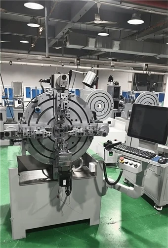
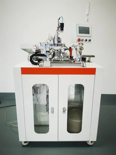
Consistent winding quality comes from consistent winding equipment. KIOXIA designs and manufactures transformer coil winding machines in Tianjin, China, covering toroidal, bobbin and special-purpose winding, with stable tension control for fine and flat wire and options for custom requirements.
Whether you need to wind micro coils with thousands of turns or high-current windings, our engineers can help you select the right configuration. Visit transformercoilwindingmachine.com or send us your coil specification to get a tailored recommendation and quotation.
You may be interested in:
Why Are High-Power Transformers More Likely To Use Flat Copper Wire Instead Of Round Copper Wire?
Toroidal Transformer Failure: Causes & Prevention
Key Machinery Required To Build A Semi-Automated Transformer Factory From Scratch
Types Of Coils Used in Electrical Engineering