

Coils used in electrical engineering are classified by shape - from a compact flat coil to a curved saddle coil - and by the job they do in a circuit, whether sensing a signal, producing a magnetic field, or transferring power wirelessly.
Every type works on the same principle: current flowing through wound turns of wire creates a magnetic field, and a changing field in turn induces voltage in nearby turns. What separates one coil type from another is geometry, core material, and turns count, which together set its inductance, resistance, and field pattern.
Below, we cover the physics and formulas that apply to all coils, then walk through each major type by shape and function, and finish with what each one requires from the machine that winds it.

I. How Do Coils Work, and What Determines Their Behavior?
How do coils work? A coil stores energy in a magnetic field created by current through its turns, and three formulas capture almost everything an engineer needs to size one: the magnetic field produced, the inductance, and the DC resistance.
Magnetic field of a coil (long solenoid):
B = (μ₀ × N × I) / l
Coil inductance formula (air core):
L = (μ₀ × μr × N² × A) / l
Coil resistance:
R = (ρ × L_wire) / A_wire
Where:
B = magnetic flux density (T), L = inductance (H), R = resistance (Ω)
μ₀ = 4π × 10⁻⁷ H/m, μr = relative permeability of the core (1 for air)
N = number of turns, I = current (A), l = coil length (m), A = coil cross-sectional area (m²)
ρ = wire resistivity (copper ≈ 1.68 × 10⁻⁸ Ω·m), L_wire = total wire length (m), A_wire = wire cross-section (m²)
Worked example: an air-core coil with 500 turns, 20mm mean diameter (10mm radius), 100mm length, wound with 0.5mm copper wire, carrying 2A:
Magnetic field: B = (4π×10⁻⁷ × 500 × 2) / 0.1 ≈ 12.6 mT
Inductance: L = (4π×10⁻⁷ × 1 × 500² × π×0.01²) / 0.1 ≈ 0.99 mH
Wire length: 500 × π × 0.02 ≈ 31.4 m, so R = (1.68×10⁻⁸ × 31.4) / (π × 0.00025²) ≈ 2.7 Ω
a. why turns count matters most
Inductance scales with N², so doubling turns quadruples inductance, while resistance only roughly doubles - which is why turns accuracy on the winding machine matters so much for inductors.
b. why wire gauge and resistance trade off
A thinner wire fits more turns in the same space but raises resistance, adding heat loss; coil design is always a balance between inductance target, current rating, and available winding window.
II. What Are the Main Coil Types by Shape?
Shape determines how the field is distributed in space, and each geometry exists because it solves a particular layout or field-pattern problem.
| Coil Type | Shape / Structure | Typical Use |
|---|---|---|
| Solenoid | Cylindrical, turns along a straight axis | Relays, actuators, simple inductors |
| Toroidal coil | Wound around a ring core | Chokes, current transformers, low-leakage inductors |
| Flat coil | Turns in a single plane, spiral | Wireless charging, sensors, thin planar inductors |
| Rectangular coil | Turns forming a rectangular loop | Magnetizers, large-area sensors, linear actuators |
| Saddle coil | Turns curved to follow a cylinder surface | Magnetic resonance, uniform transverse-field generation |
a. example: a flat coil production scenario
Consider a manufacturer of wireless charging pads producing a flat spiral coil of about 40 turns per unit. A hand-wound or loosely controlled process lets turn spacing drift, and that spacing shifts inductance enough that a noticeable share of coils fails the target tolerance at final test. Moving to a programmable winding setup with controlled turns count and wire tension brings spacing, and therefore inductance, within tolerance reliably - the difference between a production line that needs constant sorting and one that doesn't.
Producing flat, rectangular, or other non-standard coil shapes and struggling with turns or spacing consistency? Contact our team for a winding solution matched to your coil geometry.
b. why non-standard shapes need specialized winding
A rectangular coil or saddle coil can't be wound with a simple round-bobbin spindle - the machine has to hold the formed shape and control wire placement through corners and curves, which is why rectangular CNC winding machines exist as their own equipment category.

III. What Coils Are Used for Sensing and Measurement?
Sensing applications use coils to detect a changing magnetic field rather than to create one, converting it to a measurable voltage.
a. sensing coil and pickup coil
A sensing coil responds to the presence or change of a magnetic field - for example, detecting metal proximity or measuring current - while a pickup coil is a closely related type that captures a signal from a moving or varying source, as in guitar pickups, tachometers, and vibration sensors.
b. why sensing coils demand tight turns control
Because output voltage is proportional to turns count, any turn-to-turn variation between units changes sensitivity directly, which is why sensor manufacturers care more about repeatability than raw winding speed.
IV. Which Coils Create Magnetic Fields in Motors, Relays, and Magnetizers?
Coils that create fields rather than sense them fall into several named types depending on where they sit in a machine.
| Coil Type | Role |
|---|---|
| Excitation coil | Produces the magnetizing flux that drives a machine or core |
| Field coil | Creates the main magnetic field in a DC motor or generator stator |
| Armature coil | Carries load current in the rotating or stationary part where voltage is induced and torque produced |
| Trip coil | Energizes to release a latch and open a circuit breaker |
| Magnetizing coil | Generates a strong pulsed field to magnetize permanent magnets |
| Degaussing coil | Produces a decaying alternating field to remove residual magnetization |
a. how field and armature coils work together
In a DC machine the field coil sets up the flux, and the armature coil cuts that flux to produce torque or generated voltage - two coil types with different wire gauges, turns counts, and thermal demands inside the same machine.
b. why trip and magnetizing coils face special stress
A trip coil must respond reliably after sitting idle for years, and a magnetizing coil handles extremely high pulse currents, so both rely on consistent winding, good insulation, and tight turns accuracy to survive repeated stress.

V. What Coils Power Wireless Charging, RFID, and NFC?
Short-range wireless systems use coils as antennas coupling energy or data through a magnetic field.
a. wireless charging coil, RFID antenna coil, and NFC coil
A wireless charging coil transfers power across a small air gap using a flat spiral, an RFID antenna coil reads and powers passive tags at 13.56 MHz or lower frequencies, and an NFC coil is a compact flat coil operating at 13.56 MHz for short-range tap interactions.
b. which standard governs proximity coupling
Contactless proximity card and NFC communication at 13.56 MHz is specified in ISO/IEC 14443, which defines the physical and RF requirements these antenna coils must support - and is why antenna coil inductance and Q factor are held to tight tolerances in production.
VI. How Do You Choose the Right Coil Type?
| Design Priority | Coil Type to Consider |
|---|---|
| Low stray field, compact choke | Toroidal coil |
| Thin profile, planar layout | Flat coil |
| Large uniform field area | Rectangular coil |
| Transverse uniform field around a cylinder | Saddle coil |
| Plunger or actuator force | Solenoid |
| Short-range wireless coupling | Flat spiral (wireless charging / NFC / RFID) |
a. matching the winding method to the coil
The shape that suits the electrical design also dictates the winding method - toroids need toroidal winders, rectangular coils need rectangular winders, and stator or field coils need stator winding equipment - so the coil choice and the machine choice should be made together, not sequentially.
VII. Which KIOXIA Machine Winds These Coil Types?
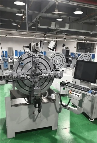
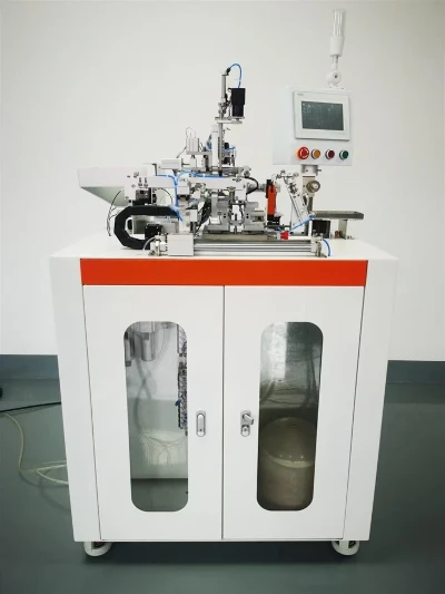
KIOXIA Light Ring Equipment Group's lineup covers the main coil families discussed above: toroidal CNC winding machines such as the KX-7005 for chokes and current transformers, rectangular and spring-type CNC coil winding machines, multi-axis parallel winding machines for bobbin and transformer coils, and stator coil production machines for motors.
Each shares the programmable turns counting and tension control that keep inductance, resistance, and field strength predictable from the first coil to the thousandth.
If you are unsure which machine type fits your coil geometry and volume, working with an experienced coil winding machine manufacturer on a short spec review - core size, wire gauge, turns count, and target output - is the fastest way to match equipment to your design.
Explore the full lineup at transformercoilwindingmachine.com to find a winding solution for your coil type.
You may be interested in:
Why Are High-Power Transformers More Likely To Use Flat Copper Wire Instead Of Round Copper Wire?
Toroidal Transformer Failure: Causes & Prevention
Key Machinery Required To Build A Semi-Automated Transformer Factory From Scratch